|
Sparking seen on commutator of DC motor...
|
|
|
...Read further to know more about the reasons |
|
|
Sparks are often seen on the commutator, below the carbon
brushes. There are many reasons for this. Minute observations can reveal the
casue. One needs to check if..... 1. Sparking occurs
only when the load and speed are increased. 2. Sparks are
yellowish in color and do not have blue tinge. 3. Sparking is
intermittent and occurence is unpredictable. Out of many causes, the following are a few. a) Inter turn short in the armature winding. Current waveform in
such cases is seen as under.
b)
Defective interpole winding can also cause sparking. If the position of the
brush holder is disturbed the following steps can be used to adjust it to
normal position, assuming that the interpoles are ok. -
Disconnect the motor totally. -
Remove armature connections. -
Apply 230 volts AC voltage to the field winding. -
Measure the induced voltage in the armature on the carbon
brushses. ( across the terminals where DC leads from the drive were connected
) -
Adjust ( rock the rocker slowly forward and backward ) the
rocker till the voltage induced is lowest. -
Tighten the rocker position at this point. c)
Sparks yellow in color indicate that these are caused due to uneven surface of commutator.
Particles of carbon from the brushes are flying off due to mechanical impact
on the brush tips. Making the commutator smooth on a lathe machine may solve
this problem. For motors with higher ratings, one will find that the carbon
brushes are split in two slabs and are sandwitched together. Each slab has
independent copper pig tails which are made parallel on the brush holder.
This construction has following advantages. 1. The air gap between the two slabs
gives additional cooling area for the heat to dissipate, keeping brush
cooler. 2. Uneven commutator segments do not make
shorting of segments impossible. With two slabs moving up and down independently, allow shorting of
segments possible. For smooth commutation of current it is necessary that the
neighbouring segments are shorted to each other
during commutation. 3. d) Worn out brushes… Worn
out brushes also cause sparking on the commutator. There is an engraved
line on each carbon brush which indicates the limit upto which the brush
could be used. e) Low pressure on
the carbon brushes…. Inadequate spring tension can also cause brushes to jump
easily which reflects in sparking. Pulling the lead of a carbon brush by hand
up to one or two centimeters and releasing it could give an ideas if spring
has lost its tension. Comparative checking with other brushes can point out
to a defective spring. Dust and accumulation of other oily or sticky material
around the brush can restrict easy movement of the brushes inside the barss
holders. Cleaning with a piece of cloth can help solving this problem. Some brushes have additional leads of wire embeded in the
brush. These are thinner wires as compared to the main current carrying
braided wires. These wires are connected to a relay of PLC in the control
panel. Wearing out of brushes beyond usable limit makes these lead touch each
other. This is detected by a relay of PLC input to give an Alarm. |
|
|
|
|
|
|
|
|
|
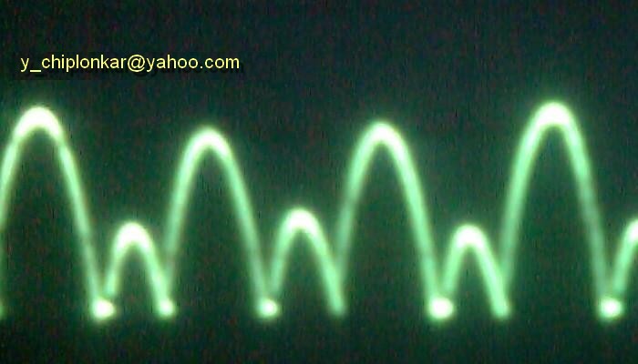
Here is a photograph of current waveform with all 6 thyristor
firing. However, all the current peaks are not of same amplitude. This means
that the motor is taking high current for some time and a lower current for
some time. As explained above, uneven mechanical friction can NOT cause this.
Because, as you can see, each current peak lasts for hardly 3 milliseconds.
Mechanical non uniformity in friction or load can not change that fast. The
reason for this uneven current peaks is always from electrical side.
There are two possibilities. a) First possibility
is that the firing of all 6 thyristors itself is uneven or unbalanced. This
can be verified by bypassing Ramp, speed amplifier, current amplifier and
connecting the drive in OPEN loop mode. i.e. by giving a dc signal of firing
thyristors directly from a potentiometer to the firing circuit. ( See the
explaination in the link "Fuses blow" ). The motor must be operated very
carefully in this mode as there are no protections of current limit etc. A
small mistake or rough handling of the potentiometer can cause a big jerk or
shock to the mechanical parts. If the current waveform does not change its
shape ( uneven peaks ) then it can be concluded that the Phase-Shift circuit
components in the Firing Circuit are not matched properly. In analog Drive,
one can check values of all 6 resistors and 6 capacitors which give required
phase shift for firing pulses. The resistors are usually of 1 % tolerence
levels. All must be precisely same. If the current waveform becomes smooth
with all 6 peaks of current of same amplitude, then it can be concluded that
the cause for uneven peaks lies in the firing signal coming from the output
of current amplifier b) Output of the
current amplifier, when seen on oscilloscope, will show wavy dc signal.
Incorrect adjsutment of Gain of the amplifiers( both speed and current )
causes this signal to be wavy. Reduce the gain to make the DC level more like
a straight line. If the gain adjustment does not solve the problem, then
another source which is likely is bad tachogenerator. Missing dc voltage on
some commutator segments of the tachogenerator can cause the output of the
current amplifier to becomve wavy. For more on DC motors, and associated testing etc.Click here...
|
Download PDF version of the pages here...
|
|
|
|
|
|
|
|
|
|
|
|
|
|
|
|
|
|
|
|
|
|
Speed control not satisfactory
|
|
|
|
|
Your comments and suggestions please
|
|
Drive stops all off a sudden..
|
|
|
|
|
|